WL-MIO Multipurpose I/O Process Controller
Application Note: WL-MIO-AN-10001
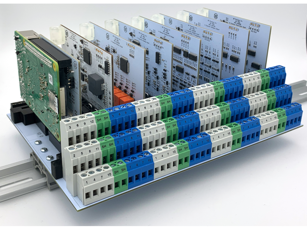
WL-MIO Quick Start Guide
Quick Start Guide for the The WL-MIO Multipurpose I/O Controller
What's Needed
- WL-MIO Backplane, Processor, I/O Modules
- 24 VDC Power SUpply
- Standard Screwdriver
- Network Port
- Computer to host control program
- DIN mounting location
Please refer to the other Appplication Notes under the "Applications" menu for more specific details on the hardware and available software.
Step 1 - Backplane Configuration
1.1 The backplane configuration applies for both the VPE-6000-N basic version and the VPE-6000-E Enclosed version.
1.2 The backplane ID is determind by the jumpers located on the rear skirt of the board betweeen the black terminal blocks.
1.3 There are four jumper locations labelled "8", "16", "32" and "64".
1.4 Each Backplane comes with an "Accessories" bag containing 4 jumpers and 1 CAN bus termination resistor
1.5 Determine the required backplane ID for the user application, and install the appropriate jumpers
1.6 Default backplane ID is "0", no jumpers installed, for single backplane applications
Back to Top
Step 2 - Power Supply Configuration
2.1 If the user application will be supplying 5 VDC through a remote power supply, ensure the power supply can supply a clean 4 A @ 5.1 VDC, the preferred voltage for a Raspberry Pi 4 application.
2.2 If the user application will only be supplying the field voltage (typically 24 VDC), ensure the 24 VDC can provide minimum 2 A plus the remote I/O device power requirements.
2.3 When using the VPE-6010 Power Supply, the on board default jumpers are installed as follows:
- Backplane Common - Enabled
- Field Supply to Backplane Enable Common - Enabled
- Field Supply to Backplane Enable +V - Enabled
- +5 VDC Output Backplane - Enabled
Back to Top
Step 3 - Inserting Modules
3.1 Any Module can be inserted into any backplane slot position
3.2 Each module position has card guide slots tp prevent module from being inserted incorreclty
3.3 The module NodeID is the "Backplane ID" determined by the backplane jumpers and the addition of the slot in which the power supply is plugged into.
Example 1: If the backplane has no jumpers and the power supply module is plugged into slot position 0, the NodeID is 0 + 0 = 0.
Example 2: If the backplane has a jumper in the "8" position and the power supply is plugged into slot postion 2, the NodeID is 8 + 2 = 10.
Back to Top
Step 4 - Wiring
- External DC Power
Wire the external DC Power to the Backplane as follows:
5.1 VDC to terminals marked "1 +5V" and "2 COM"
24 VDC to terminals marked "8 FVCC" and "9 FCOM"
- Network
The CAN bus requires a termination resistor (120 Ohm, supplied with each backplane)
For single backplane applications, install the termination resistor acros terminals marked "3 CANH" and "4 CANL"
For multiple applications, install one termination resistor on the baclplane with the processor module, and one termination resistor on the last backplane in the CAN bus network.
- I/O Device
Each I/O module has it's own wiring diagram
Each I/O module has QR code, when scanned by a smart device, the first image is the wiring diagram for the device
Each I/O module has 12 termination points
The COMMON and +V for each module can be isolated by removing the Field +V and Common jumpers (installed by factory default) on the I/O module
- Multiple WL-MIO Backplane Units
The maximum CAN bus length is 300'
Use twisted shielded cable for the CAN bus for optimum performance
The COM connection should be connected between backplanes
Ensure 2 termination resistors (120 Ohm, provided) are installed - 1 at the beginning of the CAN bus and 1 at the end of the CAN bus
Back to Top
Step 5 - Network Configuration
5.1 The WL-MIO system allows for up to 16 backplanes
5.2 Ensure each backplane has a unique ID via the jumper installation
Back to Top
Step 6 - Loading Control Program
6.1 Ensure the "libwlmio" is installed on the SD card for the processor (loaded by default if the processor is supplied by Widgetlords)
6.2 If required, download the "libwlmio" library from our GitHub site
6.3 Refer to the "Applications" menu for application notes on software demo programs