Application Note: WL-MIO-AN-36010
Power Supply
Part No.: VPE-6010
Power Supply Python Demo Software
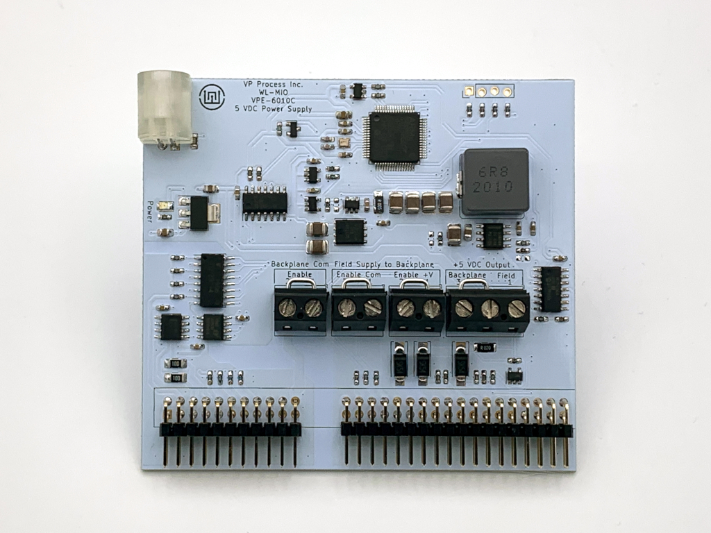
The VPE-6010 Power Supply module has 2 input voltage Channels, V1 and V2 which are auctioneered through a diode to the 5 VDC, 4 A switching power supply circuit. This module has 6 "read" channels and acts as an input module to the main system.
- V1 VDC Input
- V2 VDC Input
- +V VDC Output to the Backplane Field Connections
- +V Current Output to the Backplane Field Connections
- +5 VDC Output to the Backplane Bus Connections
- +5 VDC Current Output to the Backplane Bus Connections
By making these readings available, the user application code can monitor the power consumption of the power supply. In applications that use multiple power supplies or require the use of redundant power supplies, these readings can be used to monitor the health of the overall system power.
The power supply module can be installed in any backplane position. The NodeID referred to in the demo program is the "Backplane ID" determined by the backplane jumpers and the addition of the slot in which the power supply is plugged into.
Example 1: If the backplane has no jumpers and the power supply module is plugged into slot position 0, the NodeID is 0 + 0 = 0.
Example 2: If the backplane has a jumper in the "8" position and the power supply is plugged into slot postion 2, the NodeID is 8 + 2 = 10.
During normal operation, the status LED flashes GREEN once per second as a "heartbeat" indicator that everything is functioning normally. If the onboard firmware detects any fault conditions, the Status LED will flash either AMBER or RED.
For the following demo code to work, the "libwlmio" library has to be installed.