Application Note: WL-MIO-AN-30200


WL-MIO Modbus TCP Gateway

Responsive image

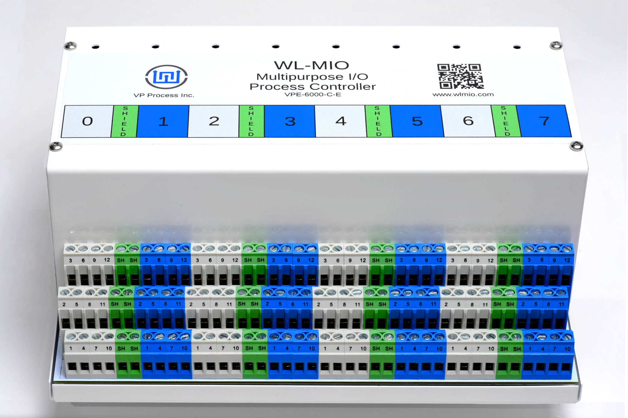
The WL-MIO Modbus TCP Gateway software allows any program such as CODESYS, OpenPLC, etc. to access the WL-MIO process controller and have read/write privileges to all modules within the WL-MIO system. This allows any existing PLC or control network with Modbus capability to take full advantage of what the WL-MIO has to offer.

This application note describes how to install the WL-MIO Modbus TCP-IP Gateway software.

Step 1

Ensure libwlmio is installed and configured as shown in the application note: WL-MIO AN-30000

Step 2

Download the wlmiomb program.

For 32 bit applications, download the following:

wget https://github.com/widgetlords/wlmiomb/releases/download/v1.1.0/wlmiomb

For 64 bit applications, download the following:

wget https://github.com/widgetlords/wlmiomb/releases/download/v1.1.0/wlmiomb_arm64.zip

Step 3

Download the wlmiomb.sh script.

wget https://raw.githubusercontent.com/widgetlords/wlmiomb/master/wlmiomb.sh

Step 4

Make sure the two files are in the same directory.

Step 5

Run:

chmod +x wlmiomb{,.sh}

Step 6

The wlmiomb.sh script does some initial steps before starting the Modbus gateway (wlmiomb). Run it with

./wlmiomb.sh

to start the gateway.

Step 7

Optional The default port is 502 but this can be changed by passing the port to wlmiomb.sh:

./wlmiomb.sh 3333
Back to Top

WL-MIO Modbus Holding Register Map


NOTE: Unit ID directly corresponds to node ID.
Register numbers are zero-indexed in decimal.

Modbus Functions and Register List

Function Description
Function 03 Read Holding Registers
Function 06 Write Single Holding Register
Function 16 Write Multiple Holding Registers

The following Registers are common to all modules

Address (Dec) Description
0000 Module uptime low word
0001 Module uptime high word
0002 Module health
0003 Module mode
0004 Module status flags
0005 UAVCAN protocol version (low byte = major, high byte = minor)
0006 Hardware version (low byte = major, high byte = minor)
0007 Software version (low byte = major, high byte = minor)
0008 Software VCS revision ID (1st/low word)
0009 Software VCS revision ID (2nd word)
0010 Software VCS revision ID (3rd word)
0011 Software VCS revision ID (4th/high word)
0012 Module UUID (1st/low word)
0013 Module UUID (2nd/word)
0014 Module UUID (3rd/word)
0015 Module UUID (4th/word)
0016 Module UUID (5th/word)
0017 Module UUID (6th/word)
0018 Module UUID (7th/word)
0019 Module UUID (6th/high word)
0020 Module Name (1st word) Low byte is first character, high byte is second
0021 Module Name (2nd word)
0022 Module Name (3rd word)
0023 Module Name (4th word)
0024 Module Name (5th word)
0025 Module Name (6th word)
0026 Module Name (7th word)
0027 Module Name (8th word)
0028 Module Name (9th word)
0029 Module Name (10th word)
0030 Module Name (11th word)
0031 Module Name (12th word)
0032 Module Name (13th word)
0033 Module Name (14th word)
0034 Module Name (15th word)
0035 Module Name (16th word)
0036 Module Name (17th word)
0037 Module Name (18th word)
0038 Module Name (19th word)
0039 Module Name (20th word)
0040 Module Name (21th word)
0041 Module Name (22th word)
0042 Module Name (23th word)
0043 Module Name (24th word)
0044 Module Name (25th word)
0045 Software CRC (1st/low word)
0046 Software CRC (2nd word)
0047 Software CRC (3rd word)
0048 Software CRC (4th/high word)
Back to Top

VPE-6010 Power Supply

Address (Dec) Description
0049 Sample interval in milliseconds
0050 5V rail current draw in mA
0051 5V rail voltage in mV
0052 24V rail input voltage 1 in mV
0053 24V rail input voltage 2 in mV
0054 24V rail voltage in mV
0055 24V rail current draw in mA
Back to Top

VPE-6030 Relay Module

Address (Dec) Description
0049 Relay 1 on/off
0050 Relay 2 on/off
0051 Relay 3 on/off
0052 Relay 4 on/off
Back to Top

VPE-6040 SDAFE Analog Input Module

Address (Dec) Description
0049 Sample interval in milliseconds
0050 Channel 1 reading
0051 Channel 2 reading
0052 Channel 3 reading
0053 Channel 4 reading
0054 Channel 1 mode (0 = 5V, 1 = 20mA, 2 = 10V)
0055 Channel 2 mode (0 = 5V, 1 = 20mA, 2 = 10V)
0056 Channel 3 mode (0 = 5V, 1 = 20mA, 2 = 10V)
0057 Channel 4 mode (0 = 5V, 1 = 20mA, 2 = 10V)
0058 Channel 1 counts
0059 Channel 2 counts
0060 Channel 3 counts
0061 Channel 4 counts
Back to Top

VPE-6050 Analog mA Output Module

Address (Dec) Description
0049 Channel 1 output in mA
0050 Channel 2 output in mA
0051 Channel 3 output in mA
0052 Channel 4 output in mA
0053 Channel 1 mode (0 = source, 1 = sink)
0054 Channel 2 mode (0 = source, 1 = sink)
0055 Channel 3 mode (0 = source, 1 = sink)
0056 Channel 4 mode (0 = source, 1 = sink))
Back to Top

VPE-6060 Digital Input Module

Address (Dec) Description
0049 Sample interval in milliseconds
0050 Channel 1 reading (low word)
0051 Channel 1 reading (high word)
0052 Channel 2 reading (low word)
0053 Channel 2 reading (high word)
0054 Channel 3 reading (low word)
0055 Channel 3 reading (high word)
0056 Channel 4 reading (low word)
0057 Channel 4 reading (high word)
0058 Channel 1 mode (0 = basic/discrete, 1 = frequency, 2 = pulse counter)
0059 Channel 2 mode (0 = basic/discrete, 1 = frequency, 2 = pulse counter)
0060 Channel 3 mode (0 = basic/discrete, 1 = frequency, 2 = pulse counter)
0061 Channel 4 mode (0 = basic/discrete, 1 = frequency, 2 = pulse counter)
0062 Channel 1 bias (0 = none, 1 = PNP, 2 = NPN)
0063 Channel 2 bias (0 = none, 1 = PNP, 2 = NPN)
0064 Channel 3 bias (0 = none, 1 = PNP, 2 = NPN)
0065 Channel 4 bias (0 = none, 1 = PNP, 2 = NPN)
0066 Channel 1 polarity (0 = rising edge, 1 = falling edge)
0067 Channel 2 polarity (0 = rising edge, 1 = falling edge)
0068 Channel 3 polarity (0 = rising edge, 1 = falling edge)
0069 Channel 4 polarity (0 = rising edge, 1 = falling edge)
Back to Top

VPE-6070 Analog Voltage Output Module

Address (Dec) Description
0049 Channel 1 output in mV
0050 Channel 2 output in mV
0051 Channel 3 output in mV
0052 Channel 4 output in mV
Back to Top

VPE-6080 Thermistor Input Module

Address (Dec) Description
0049 Sample interval in milliseconds
0050 Channel 1 reading in Kelvin (scaled by 10)
0051 Channel 2 reading in Kelvin (scaled by 10)
0052 Channel 3 reading in Kelvin (scaled by 10)
0053 Channel 4 reading in Kelvin (scaled by 10)
0054 Channel 5 reading in Kelvin (scaled by 10)
0055 Channel 6 reading in Kelvin (scaled by 10)
0056 Channel 7 reading in Kelvin (scaled by 10)
0057 Channel 8 reading in Kelvin (scaled by 10)
0058 Channel 1 enable (0/1)
0059 Channel 2 enable (0/1)
0060 Channel 3 enable (0/1)
0061 Channel 4 enable (0/1)
0062 Channel 5 enable (0/1)
0063 Channel 6 enable (0/1)
0064 Channel 7 enable (0/1)
0065 Channel 8 enable (0/1)
0066 Channel 1 beta value
0067 Channel 2 beta value
0068 Channel 3 beta value
0069 Channel 4 beta value
0070 Channel 5 beta value
0071 Channel 6 beta value
0072 Channel 7 beta value
0073 Channel 8 beta value
0074 Channel 1 t0 value in Kelvin (scaled by 100)
0075 Channel 2 t0 value in Kelvin (scaled by 100)
0076 Channel 3 t0 value in Kelvin (scaled by 100)
0077 Channel 4 t0 value in Kelvin (scaled by 100)
0078 Channel 5 t0 value in Kelvin (scaled by 100)
0079 Channel 6 t0 value in Kelvin (scaled by 100)
0080 Channel 7 t0 value in Kelvin (scaled by 100)
0081 Channel 8 t0 value in Kelvin (scaled by 100)
0082 Channel 1 counts
0083 Channel 2 counts
0084 Channel 3 counts
0085 Channel 4 counts
0086 Channel 5 counts
0087 Channel 6 counts
0088 Channel 7 counts
0089 Channel 8 counts
Back to Top