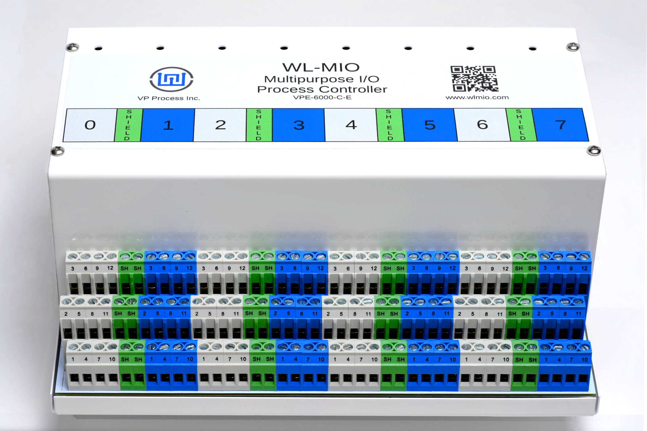
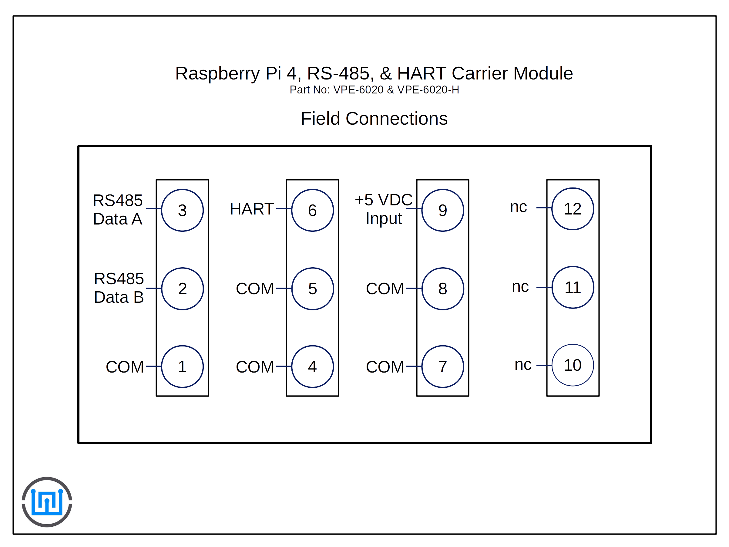
The RS485 connections are located on terminal blocks 1 (Common), 2 (Data B) and 3 (Data A).
This application note describes how to install and use the WL-MIO Modbus RTU RS485 Interface.
NOTE: All examples use the minimalmodbus.py program.
In the Widgetlords Electronics product lines that include a RS485 driver, the direction whether Receive or Transmit is controlled directly via a GPIO line. Most programs available such as libmodbus or minimalmodbus for the Raspberry Pi assume the direction control is performed by the RS845 driver circuit. Typically this would be done by a 555 timer, a FTDI chip or similar circuit.
The driver chip used in our circuits is the standard half duplex RS485 chip, the Texas Instrument SN65HVD75D or equivalent.
The /RE and DE lines are tied together, when set high the transceiver is in receive mode, when set low, the transceiver is in transmit mode.
Userspace application code normally drives the direction bit of the RS845 transceiver. However, when using Modbus application libraries that do not have direct access to the direction control GPIO line, we have come up with a solution.
We have available an executable program that runs in the background which takes over the serial port and automatically controls the direction control for all standard baud rates. This program has been tested with minimalmodbus and Node-Red.
The program is called "modbusd" and can be downloaded here:
Download the executable file "modbusd"
Step 1
Ensure libwlmio is installed and configured as shown in the application note: WL-MIO AN-30000
Step 2
Install the gpiod2 library
sudo apt install libgpiod2
Step 3
Load the "modbusd" executable program into a file folder or desktop.
Step 4
In the RPi config, ensure the uart is enabled.
Step 5
In the RPi config, ensure the serial console is disabled.
Step 6
Change the permissions for the modbusd program:
chmod +x modbusd
Step 7
For help, run:
./modbusd --help
-d, --driver=GPIO GPIO pin used for transmit enable
-s, --stty=FILE Specify serial TTY
-v, --vtty=FILE Specify virtual TTY
-?, --help Give this help list
--usage Give a short usage message
Step 8
For applications using Modbus RS485 (including Node-Red) and Widgetlords products, run in the background the program:
./modbusd
This will create the "/tmp/modbus" program that controls the GPIO Direction Control Pin automatically.
Applications
This method works equally well with libmodbus or minimalmodbus
Using minimalmodbus-1.0.2
The following code example assumes the end user has gone thru and understands the minimalmodbus documentation.
This code example use the VP-EC-RDU-MINI Modbus RTU RS485 LCD Display as a test unit.
#Read and Write values from the VP-EC-RDU-MINI LCD Display via Modbus RTU RS485

from time import sleep
import minimalmodbus

rdu = minimalmodbus.Instrument('/tmp/modbus', 100)  		# port name, slave address (in decimal)
rdu.serial.baudrate = 19200

while True:

    temperature = str(rdu.read_register(50)/100)		# Read temperature value (Scaled x 100) from Register 50
    pushbuttons = str(rdu.read_register(58))			# Read Pushbutton values from Register 58

    rdu.write_string(0,  " Hello WL-MIO World ", 10)		# Write LCD Line 1
    rdu.write_string(10, " Temperature        ", 10)		# Write LCD Line 2
    rdu.write_string(20, " " + temperature + " Deg C", 10)	# Write LCD Line 3
    rdu.write_string(30, " Pushbuttons = " + pushbuttons, 10)	# Write LCD Line 4

    sleep(.5)
Back to Top