Application Note: WL-MIO-AN-30300
WL-MIO CODESYS Application Tutorial
Overview
Since CODESYS does not have native support for the WL-MIO hardware a Modbus TCP Gateway will be used. CODESYS applications will interact with this gateway via Modbus to read and write I/O points. To install the gateway see the Application Note WL-MIO-AN-30200
Requirements
1. CODESYS IDE with Raspberry Pi package installed on a system with network access to the Raspberry Pi.
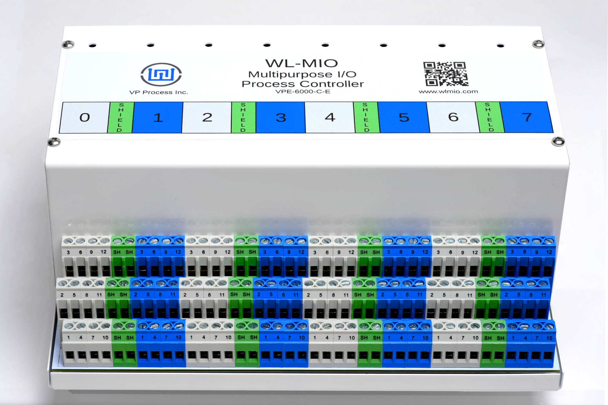
2. WL-MIO system with a VPE-6040 Analog Input Module with ID 2 and a VPE-6030 Relay Output Module with ID 3.
3. Modbus TCP gateway installed and running.
Step 1
Steps 2-5 can be skipped if your Raspberry Pi has the CODESYS runtime already installed and running.
Step 2
Start the CODESYS IDE.
Step 3
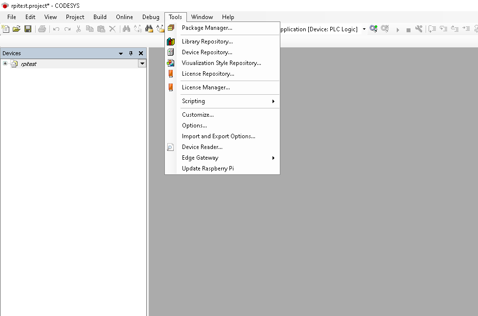
Open “Tools” menu and click “Update Raspberry Pi”.
Step 4
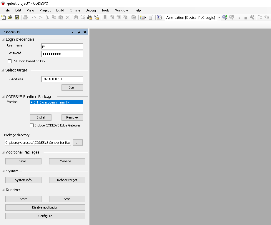
Configure the window on the left as shown below and then click “Install” under “CODESYS Runtime Package”.
Step 5
Click “Start” under “Runtime”.
Step 6
Download the project rpitest.projectarchive somewhere.
This is a simple project that reads an analog input value and turns on a relay if the input threshold value is crossed.
Step 7
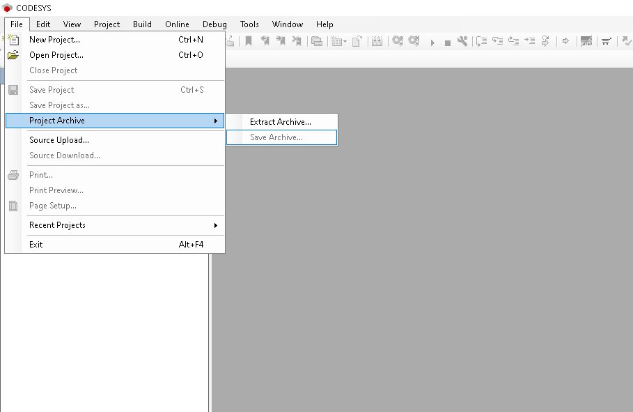
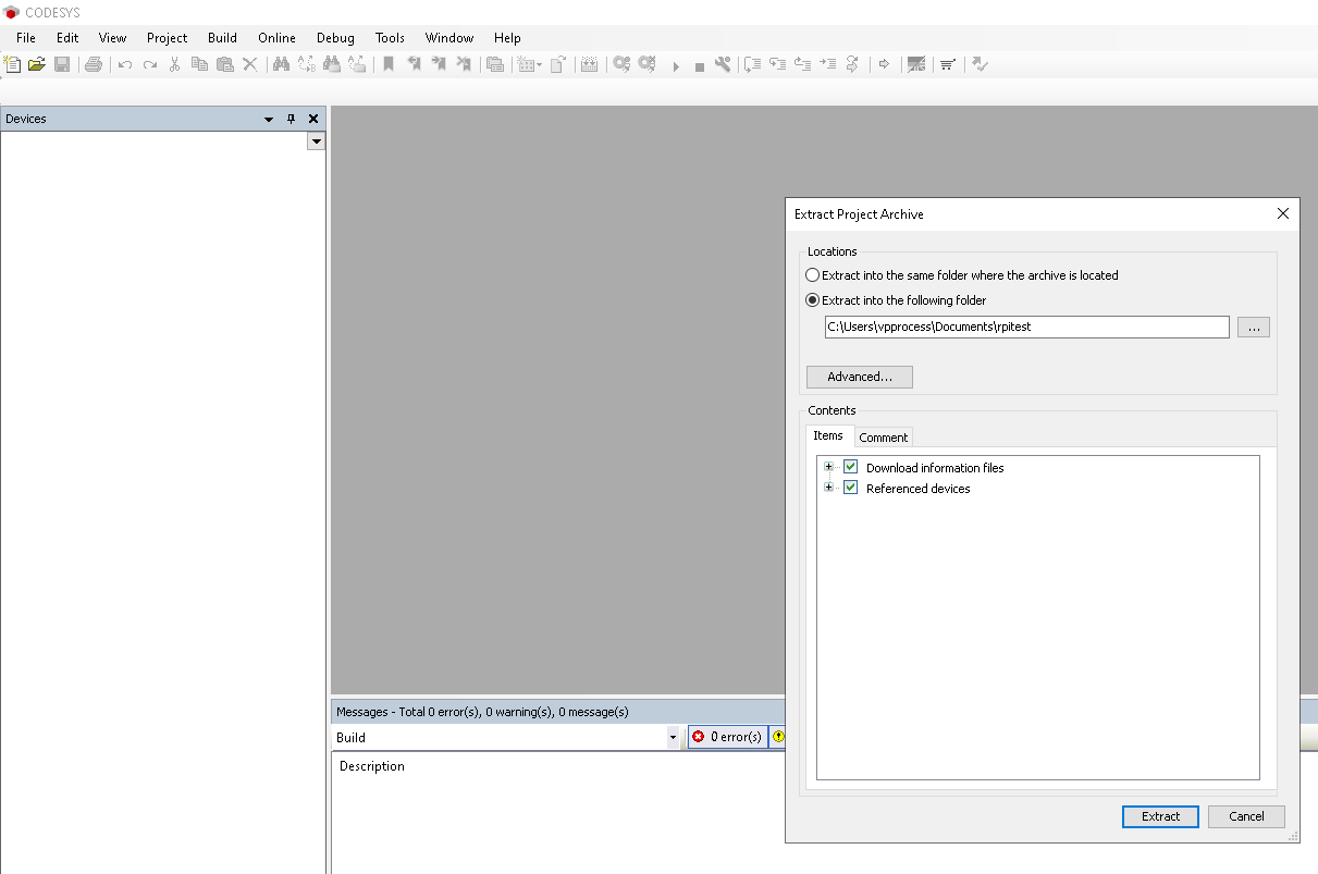
Select “File” → “Project Archive” → “Extract Archive”.
Step 8
Extract the project.
Step 9
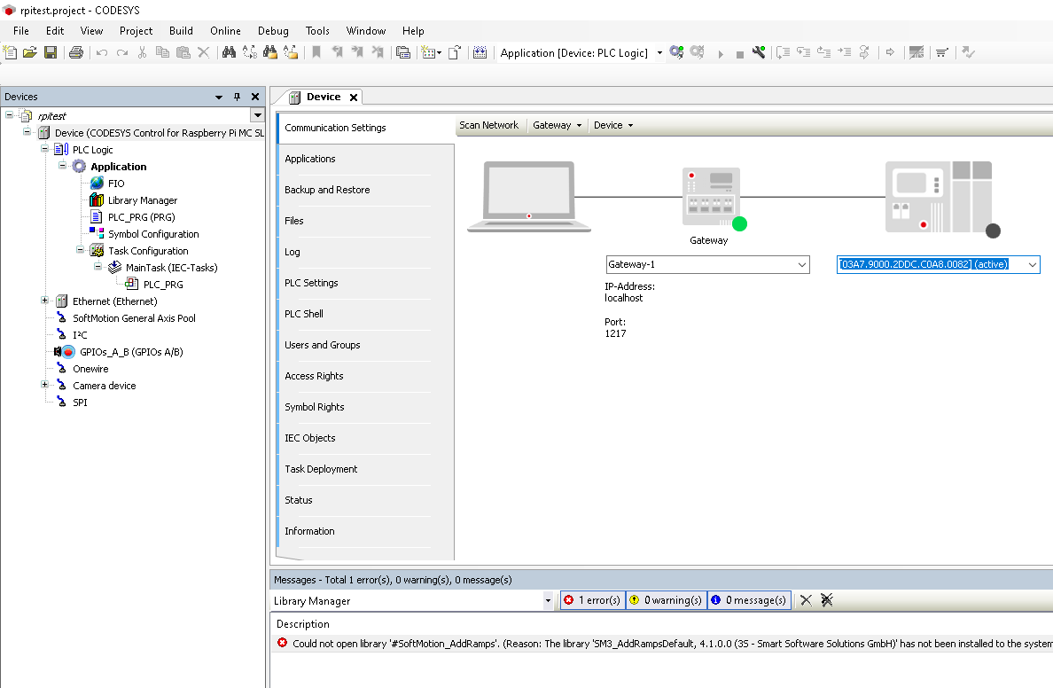
When the project is opened, double-click the “Device” entry in the tree on the left. Then select “Communication Settings” from the center window. Then enter the IP address of your Raspberry Pi in the right-most dropdown and press enter. (Highlighted in the screenshot)
Step 10
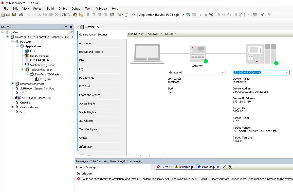
You should see something like the below screenshot.
Step 11
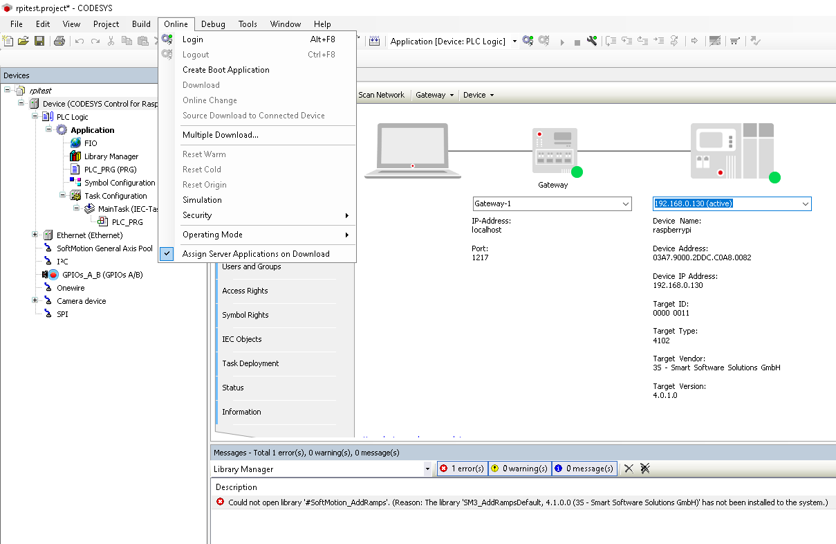
Now go to “Online” → “Login” to connect the IDE to the Raspberry Pi. If CODESYS asks you to update the application, click yes.
Step 12
If the application is stopped it can be started by right-clicking on “Application” and clicking “Start”.
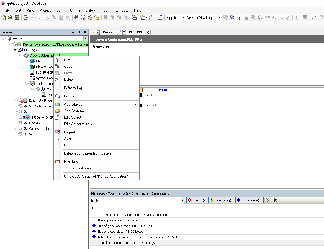
Step 13
Once the application is running you can apply more than 2.5V to the first channel of the VPE-6040 module with ID 2 to cause a relay to turn on. The code for this can be seen in the PLC_PRG file.
Back to Top